
Ground Bearing Pressure Fundamentals
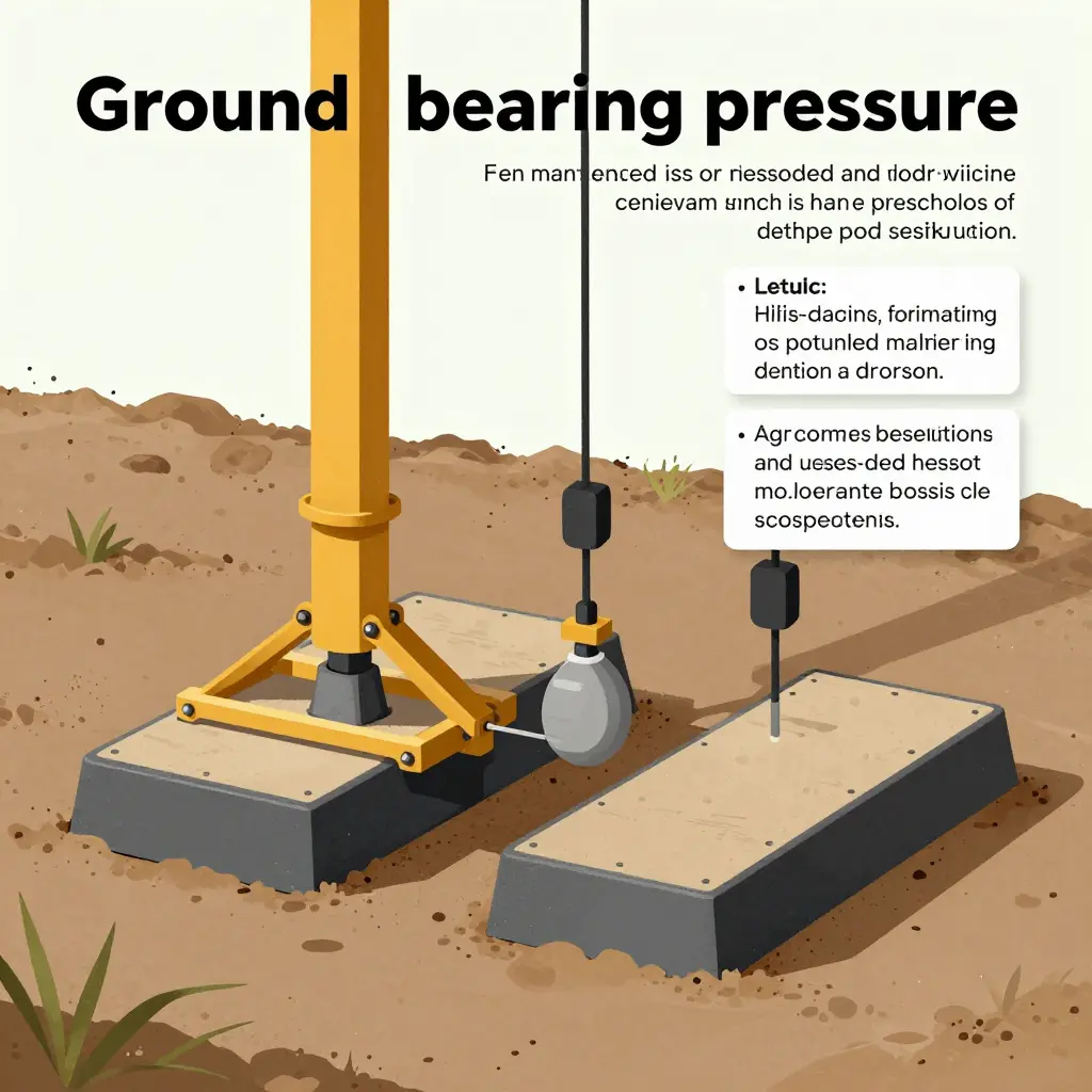
Ground bearing pressure is the stress a crane imposes on the soil under its supports: the reaction force at each support divided by the area of contact. When a crane lifts a load, its own weight and the load’s weight combine into downward reactions at the outriggers. Those reactions travel through the outrigger float, the steel foot at the base of the jack cylinder, before they reach the ground.
How Outrigger Floats and Pads Transfer Force
A bare outrigger float concentrates force on a small area, so pressure climbs quickly. A crane mat or a wider outrigger pad increases the contact area and lowers that pressure in proportion: double the pad footprint and you roughly halve the pressure. Mats do not reduce the load; they spread it. Properly rated equipment from professional lifting vehicle manufacturers helps, but it does not replace a site-specific soil assessment.
Load Distribution Changes With Configuration
The reaction at each outrigger is never fixed. As the boom swings, the radius grows, or the counterweight changes, the crane’s center of gravity moves. The outrigger nearest the load carries more force, while the opposite one may carry very little. A heavier counterweight shifts force toward the rear outriggers. A longer radius increases the overturning moment, concentrating load on a single corner.
Why Outrigger Pad Sinking Happens
When the soil’s bearing capacity is lower than the calculated pressure, the float presses into the ground. Outrigger pad sinking follows, tilting the crane and changing the geometry the load chart assumes. Load charts list lifting capacity, not soil strength, so they stay silent while the ground fails beneath the pads.
How the Load Actually Travels Into the Ground
An outrigger does not simply put weight on the surface. It funnels force downward and outward, the way a pyramid spreads its base. The diagram below shows the path: a concentrated point load from the outrigger beam reaches the pad, then fans out wider and deeper into the soil underneath.
What matters is the shape of that spread. Right at the pad, bearing pressure is at its highest. Deeper down, the same total load is distributed across a larger area, so pressure per unit area falls. That is why a wide pad helps: it widens the cone of influence from the very top, lowering the peak stress the surface soil must carry.
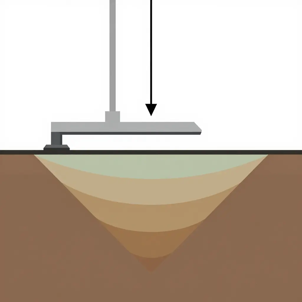
When the soil’s bearing capacity is lower than that peak pressure at the pad interface, the ground yields. The pad does not fail; the soil underneath it does. The trouble starts in the difference between what the load chart assumes and what the ground can carry. Understanding professional rigging and lifting equipment design helps put the full load path in perspective, from the crane’s frame down to the soil interface.
Why Soft Ground Behaves Differently Under Outrigger Loads
Firm ground and soft ground respond to the same outrigger load in different ways. A load chart gives the reaction each pad pushes into the soil; it says nothing about whether that soil can push back safely. Outrigger pad sinking begins in that missing answer.
Compressibility comes first. Firm, well-graded soil resists deformation because its particles interlock and drain freely. Soft ground holds voids, organic matter, and trapped water that compress under load, so the pad moves down instead of the ground pushing back. Makers of professional lifting equipment design pads to spread pressure evenly; they cannot compensate for soil that keeps yielding.
The second factor is shear strength. Soil bearing capacity depends on how much shear stress the ground can absorb before it fails. Soft ground has low shear strength, so once pressure under a pad exceeds that limit, the soil shears and the pad breaks through. When that happens suddenly, the crane can tip before the operator reacts.
Consolidation adds time. In saturated clays, pore water must drain before the soil settles permanently, so deformation continues slowly under sustained load. Settlement is a process, not an instant event. A crane that looks perfectly stable on arrival can sink minutes later.
Lateral squeeze is the fourth mechanism. Soft soil moves sideways as well as down. When a pad loads a single spot, weaker soil is displaced laterally, the pad edge loses support, and the effective contact area shrinks. Because the movement happens below the surface, it is easy to miss.
Together these mechanisms erode crane stability. A load chart assumes a dependable bearing surface, but soft ground changes under load. Reading the soil, not just the chart, is the first step toward a safe setup.
A load chart rates the crane, not the ground beneath it. The chart assumes a level, stable, adequately supporting surface, a premise that ends the moment the outrigger pad meets real soil. Line up published ratings against the ground bearing pressure those picks actually demand, and the difference is plain.
| Crane Configuration / Load Condition | Load Chart Rating | Required Ground Bearing Pressure | Typical Soil Response | Observed Risk of Outrigger Pad Sinking |
|---|---|---|---|---|
| 50 t all-terrain, full outriggers, boom at 30 m, level pad on compacted fill | 12 t @ 30 m radius | approx. 95 psi (6.5 bar) per outrigger pad | Firm, well-compacted material – minimal deflection | Low – pad footprint holds, no rutting |
| 50 t all-terrain, same lift, outrigger pad over soft clay | 12 t @ 30 m radius | approx. 95 psi (6.5 bar) per pad – unchanged by the chart | Clay yields slowly, then punches under sustained load | High – visible rut, pad tilt, boom drifts off radius |
| 100 t truck crane, 40 t pick at 12 m, outrigger mats on loose sand | 40 t @ 12 m radius | approx. 140 psi (9.7 bar) per pad | Loose sand settles gradually as grains rearrange | Moderate to high – progressive settlement during the lift |
| 25 t carry deck crane, 8 t pick, single outrigger set on saturated silt | 8 t @ 18 m radius | approx. 60 psi (4.1 bar) per pad | Saturated silt loses shear strength almost instantly | Very high – sudden sink, little warning |
| 60 t rough-terrain, 15 t pick at 20 m, outrigger pad on frozen crust | 15 t @ 20 m radius | approx. 110 psi (7.6 bar) per pad | Frozen crust shatters, soft layer beneath fails | High – rapid punch-through once crust breaks |
| 130 t hydraulic truck crane, 60 t pick at 14 m, outrigger pad on engineered mat + gravel | 60 t @ 14 m radius | approx. 165 psi (11.4 bar) per pad | Gravel interlock spreads load, minimal deformation | Low to moderate – stable if mat sized correctly |
| Same 130 t crane, 60 t pick, no mats over wet topsoil | 60 t @ 14 m radius | approx. 165 psi (11.4 bar) per pad | Topsoil compresses, bearing capacity collapses locally | Very high – pad buries, outrigger floats |
| 200 t lattice truck crane, 90 t pick at 10 m, outrigger pad on firm gravel pad | 90 t @ 10 m radius | approx. 200 psi (13.8 bar) per pad | Dense gravel – elastic rebound only | Moderate – safe when subgrade is verified |
The pattern holds within each crane and lift pair: the chart rating does not change when the ground changes, because the chart describes crane geometry and stability. Required ground bearing pressure does not change either – it is a function of load and pad area. The soil is the variable. A pad can be correctly rated for the lift and still disappear into the ground, because the chart never asked the soil anything.
Operators sizing support equipment can use professional lifting vehicle solutions as a reference for how these machines are engineered for real ground conditions.
Soil Mechanics and Bearing Capacity
Whether an outrigger pad holds or sinks depends on how the ground beneath it distributes load. Soil is not a rigid solid; it is a three-phase system of mineral grains, water, and air. When a pad presses down, the soil must spread that stress over a wider area, and its ability to do so defines its soil bearing capacity. For a closer look at how lifting equipment is engineered around these forces, see this overview of professional lifting special vehicle manufacturing.
Bearing Capacity Theory
Bearing capacity is the maximum pressure soil can sustain before shear failure occurs, the point where grains slide past one another and the ground punches downward. Terzaghi’s classic model expresses this as a function of cohesion, surcharge, and the unit weight of the soil, weighted by factors that depend on the friction angle.
Allowable Bearing Pressure
Engineers do not design to ultimate capacity. They divide it by a factor of safety to obtain the allowable bearing pressure, the working stress a pad may impose. Representative values:
| Soil Type | Allowable Bearing Pressure (kPa) |
|---|---|
| Dense sand | 200 – 600 |
| Loose sand | 100 – 150 |
| Stiff clay | 150 – 300 |
| Soft clay | 25 – 50 |
| Fill / organic | 10 – 50 |
Moisture, Void Ratio, and Grain Structure
- Moisture: rising water content lowers effective stress and cohesion, softening clay and destabilizing sand.
- Void ratio: higher voids mean looser packing and greater settlement under load.
- Grain structure: angular, well-graded grains interlock and resist shear better than rounded, uniform ones.
Ground Safety Factors vs. Structural Ones
Load charts apply structural factors of safety to steel and hydraulics, which are known, consistent, and quality-controlled. Ground support is different: soil varies meter to meter, moisture shifts with weather, and nobody tests the pad location. A ground factor of safety of 2 to 3 is common, precisely because the ground is the least predictable part of the support system.
Why the Ground Under an Outrigger Pad Matters More Than the Load Chart
Load charts tell you what a crane can lift. They say almost nothing about what the ground beneath the outrigger pad can carry. Rigs that look within spec on paper still tilt, punch through, or settle several inches into soft ground the moment the boom swings out.
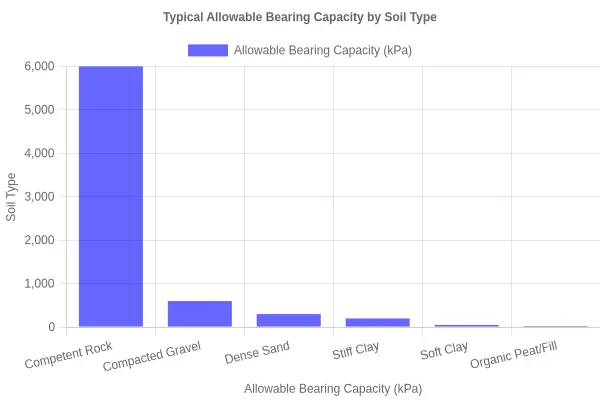
Allowable bearing capacity, the number a geotechnical engineer uses to describe how much pressure a soil can take before it fails, is not a single value. It changes sharply with soil type. The chart below compares the six ground conditions crews encounter most often.
What the Bars Tell You
The same data in a quick-reference table:
| Soil Type | Typical Allowable Bearing Capacity (kPa) |
|---|---|
| Competent Rock | 6000 |
| Compacted Gravel | 600 |
| Dense Sand | 300 |
| Stiff Clay | 200 |
| Soft Clay | 50 |
| Organic Peat / Fill | 25 |
Reading Between the Numbers
The chart shows how sharply capacity falls. From competent rock to compacted gravel you lose 90 percent of your bearing capacity, yet both feel solid underfoot. Drop to soft clay and you are down to a quarter of what stiff clay carries; organic peat or fill is roughly an eighth.
For an operator, that sets pad sizing and cribbing. A pad that spreads load safely on gravel may be far too small on soft clay, and on peat or undocumented fill no standard pad may be enough without a crane mat or a structural raft underneath.
Why the Load Chart Stays Silent
Load charts are conservative about the machine, not the geology. They assume the site assessment is done, the soil identified, and adequate ground bearing provided. Stable, level support is a given in the chart – the exact assumption that fails on a soft pad preparation.
That is why experienced crews treat site evaluation as a separate checklist item from the load chart. They ask what the ground can actually hold before they ask what the crane can lift.
Several site and setup conditions accelerate outrigger pad sinking, and each one deserves a quick inspection before the boom goes up.
- Water saturation: saturated voids destroy the friction between soil particles, so firm-looking ground can liquefy the moment load is applied.
- Recent rainfall: even a day or two of rain turns the top layer of soft ground into a sponge that can no longer carry design pressure.
- Disturbed or backfilled soil: previously excavated ground is looser than native material and seldom returns to its original density.
- Poorly compacted ground: fill placed without proper lift-by-lift compaction settles unevenly and lets the pad punch downward.
- Inadequate mat area: a mat too small for the load spreads force over too few square feet, pushing ground bearing pressure beyond what the soil can hold.
- Off-level setup: a tilted pad concentrates weight on a single edge, shrinking effective contact area and speeding penetration.
- Concentrated loads from a short outrigger spread: narrow spread geometry funnels more force onto each pad, amplifying every weakness listed above.
Treat this list as a pre-lift checklist, because ground bearing pressure climbs fastest wherever several of these factors overlap. For how lifting vehicles are engineered to manage these forces, see professional lifting equipment design.
Why Load Charts Stay Silent About Ground Conditions
A load chart tells you what a crane can lift, not what the earth beneath it can hold. That distinction explains most outrigger accidents, and it is worth stating plainly.
Load Charts Only Describe the Machine
Manufacturer load charts are calculated for a crane on a firm, level, uniformly supporting surface. Ratings combine boom length, radius, counterweight and configuration, and they assume the machine itself is the only variable under stress. The chart says nothing about soil, because the chart cannot see your site. It is a structural and stability document, not a geotechnical one.
Chart-Rated Structure vs. Site-Controlled Support
Responsibility divides cleanly. The manufacturer certifies the crane structure, hydraulic components and rated capacity. The operator and site planner own everything below the outrigger pad: soil type, compaction, drainage, voids, and any buried utilities or backfilled trenches. Crane stability depends on both halves of that equation working together, yet only one half appears on the chart.
What Standards Actually Address
Design standards such as ASME B30.5 and ISO 4310 test a crane for structural strength and resistance to overturning. They verify that the machine will not buckle, tip or fail when loaded as rated. They do not test soil ground bearing pressure, because bearing capacity changes with moisture, frost, fill and disturbance. A chart that passed every structural test can still fail on soft ground.
Where Ground Assessment Belongs
That leaves ground bearing pressure and support design with the operator and site planner. Before any crane setup, someone must evaluate the surface, calculate the pressure the outriggers will impose, and select pads or mats that spread the load accordingly. Treating the load chart as proof of ground safety is a category error.
The chart assumes the ground is already solved. Solving it is the operator’s job, and it starts long before the boom goes up. Choosing the right lifting vehicle for your fleet is a separate decision best grounded in real specs; see how a professional lifting special vehicle manufacturer approaches the build.
Where the Risk Actually Concentrates
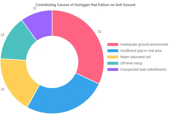
When an outrigger pad punches through soft ground, the post-incident reports rarely point to a single villain. Failure is almost always a pile-up of small, avoidable oversights, each one harmless on its own and serious in combination. The doughnut chart below shows the five contributing causes in proportion.
Reading the Slices
- Inadequate ground assessment (32%) – the largest slice by a wide margin. The ground looked solid, so nobody probed it, trenched it, or checked what was buried underneath. Surface appearance is a poor predictor of bearing capacity.
- Insufficient pad or mat area (26%) – the load was fine; the footprint was not. Undersized pads concentrate pressure into a small patch of soil instead of spreading it.
- Water-saturated soil (18%) – recent rain, a broken drain, or a high water table turns firm fill into a slurry that offers a fraction of its dry strength.
- Off-level setup (14%) – a slight tilt shifts load onto fewer outriggers, overloading one pad long before the load chart flags anything.
- Unexpected load redistribution (10%) – wind, a swinging boom, or a settling pad moves weight where the original setup never planned for it.
Why This Matters More Than the Load Chart
Load charts deal in numbers and assume the ground beneath you can carry what the pad can deliver. This breakdown tells a different story: roughly six in ten failures trace back to how the ground was read and how the load was spread, not to the crane’s rated capacity. That is the argument for treating ground preparation as an engineering step rather than a formality you rush through before the lift.
For teams choosing support equipment, work with a professional lifting special vehicle manufacturer that engineers pads and mats around actual soil behavior.
The Setup Logic Behind Every Outrigger Decision
Every crane lift on questionable ground follows the same chain of decisions. The load chart covers only the last link, while the ground beneath your outriggers decides whether the chain holds at all. The sequence runs as follows.
Ground Assessment Comes First
Before a single pad is placed, you evaluate the soil. Ask what is actually load bearing here, not what the ground looks like from the operator’s cab. Loose fill, saturated clay, and buried voids all look the same from above and behave completely differently under pressure. Probing the surface, checking for recent excavation, and noting water pooling are fast, cheap ways to flag soft or variable ground before equipment commits.
- Identify bearing capacity signs – visible rutting, sponginess underfoot, or standing water.
- Check for variability – a firm crust over soft subsoil is the classic trap.
- Confirm drainage – where water goes tells you where it will collect and soften further.
Pad or Mat Area Selection
With the soil characterized, the next decision is what to put down. The goal is not to spread weight blindly, but to reduce bearing pressure below the soil’s limit while keeping the crane level. A single pad under a firm layer can be enough; a soft, variable footprint usually calls for a mat that ties multiple outriggers into one wider bearing area.
| Site Condition | Recommended Support | Key Reason |
|---|---|---|
| Firm, uniform soil | Standard pads | Adequate bearing capacity already |
| Soft surface crust | Larger pads | Lower bearing pressure per point |
| Variable or weak subsoil | Timber or composite mats | Bridges weak zones, widens area |
| Known voids or fill | Engineered mat + survey | Reduces punch-through risk |
Verifying Load Distribution
Support selection and load verification go together. The outrigger load is not simply the crane’s weight divided by four – it shifts with boom radius, counterweight, and lift configuration. Confirm that the pressure each pad or mat imposes stays within the soil’s calculated capacity, allowing margin for the dynamic swings that occur as the load moves.
Monitoring Settlement Before and During the Lift
This is the step most crews skip and later regret. Set a reference and watch it. Before the lift, pre-load the outriggers and check for movement. During the lift, keep an eye on level gauges and pad edges. Settlement is often slow and small at first, then accelerates once the soil fails; catching that early movement is what prevents a tip or a punch-through.
- Pre-load and observe – apply load gently and watch for dip.
- Watch during the swing – maximum outrigger load rarely sits where you expect.
- Stop on movement – any creeping settlement means the setup is wrong, not the load.
For crews running support and recovery equipment alongside cranes, the same principle holds: the foundation, not the machine, decides the outcome. Stability has to be built into the hardware as well as the ground.
Frequently Asked Questions
Why do load charts omit soil conditions?
Load charts describe the crane’s structural and stability limits, not the ground beneath it. Manufacturers cannot know what soil, asphalt, or backfill a machine will stand on, so they publish rated capacities assuming a firm, level, uniformly supporting surface. The chart tells you what the crane can lift, not what the ground can hold.
How do I estimate ground bearing pressure?
Divide the total load carried by each outrigger by the area of its pad. Add the crane’s weight, counterweight, and lifted load, then distribute the force using the outrigger reaction figures in the manual. A 24-inch pad concentrates the same force over a small footprint, so pressure can exceed 1,000 psi during a heavy pick.
When is a crane mat required?
A crane mat is required whenever the calculated ground bearing pressure exceeds the soil’s verified capacity. Soft ground, recently backfilled trenches, and asphalt over voids are the most common triggers. Check with a professional lifting vehicle manufacturer or engineer when you are unsure, and add mats to spread the load across a wider area.
How does outrigger pad sinking differ from structural overload?
Outrigger pad sinking is a ground failure, not a crane failure. The machine stays within its load chart while the pad punches into soft soil, tilting the chassis and eroding crane stability. Structural overload is different: it overstresses the boom or frame no matter how firm the ground is.
How do I verify ground capacity before a lift?
Review geotechnical data, walk the site, and probe suspect areas before setup. Compare outrigger reaction values against presumptive soil capacity using a reference like the table below. Where margins are thin, add mats or relocate the crane, then document the check in the lift plan.
| Soil / Material | Presumptive Bearing Capacity (psf) |
|---|---|
| Crystalline bedrock | 12,000 |
| Sedimentary rock | 6,000 |
| Compact gravel | 5,000 |
| Stiff clay | 4,000 |
| Compact sand | 3,000 |
| Medium-stiff clay | 2,000 |
Can a larger outrigger pad fix every soft-ground problem?
No. A larger pad lowers ground bearing pressure, but it cannot compensate for a weak layer deep below the surface. If the failure plane sits well under the mat, adding area only shifts the problem sideways. Ground improvement or a wider matting platform may be the only reliable fix.
The Bottom Line: Two Capacities, One Safe Setup
Throughout this article, a single distinction kept resurfacing: load charts and ground bearing pressure answer two entirely different questions. Load charts govern structural capacity – they tell you whether the boom, chassis, and outrigger beams can carry a given lift at a given radius. They stay silent, by design, about the soil beneath the machine. Ground bearing capacity governs whether the outrigger pads actually hold, and on soft ground that number is often far lower than any chart assumes. A setup is only safe when both conditions are satisfied at once; meeting one while ignoring the other is how machines tip.
The practical takeaway is straightforward. Every crane setup plan should include a genuine ground assessment, enough pad and mat area to spread the load to a defensible bearing pressure, and active settling monitoring once the load is airborne. These are not optional extras – they are the difference between a controlled pick and an incident.
For readers who want a broader view of how lifting equipment is specified and built for real-world conditions, the professional lifting special vehicle manufacturer guide on craneliftvehicles.com is useful related reading. Treat the ground as part of the machine, and the setup stays predictable.